The (un)Official Free-moS Standard
THIS IS A WORK IN PROGRESS!
Please note that these standards are not final and are subject to change. All modules should be designed with flexibility in mind until the standards are officially adopted. This approach allows for adjustments and improvements based on feedback and practical experience, ensuring that the final standards will be robust and effective for all participants.
This standard is current as of June 2nd, 2025. Please visit the Facebook Page or check the Home Page for announcements of information about any discussion forums for standards changes. Changes discussed online will be updated here as soon as possible.
Legend
- S: Standard. All Free-moS modules and participants must conform to the requirement as stated.
- RP: Recommended Practice: These are procedures or standards that are strongly recommended.
- FAQ: Frequently Asked Questions: Explain some of the reasoning behind the standard.
1.0 Introduction
- S1.1
- Free-moS is a modular standard for S Scale (1:64) model railroading that emphasizes flexibility and realism. It allows modelers to create individual modules that can be connected in various configurations to form a larger layout. The standard specifies the dimensions, track placement, and electrical connections to ensure compatibility between modules. This approach enables hobbyists to collaborate on large, detailed layouts without being constrained by a fixed track plan.
- S1.2
- One of the key features of Free-moS is its focus on prototypical operation and scenery. Modules are designed to represent real-world locations and operations, with attention to detail in track, structures, and landscapes. This emphasis on realism enhances the overall experience for operators and spectators alike. Additionally, the modular nature of Free-moS encourages community involvement and sharing of techniques and ideas among model railroaders.
- S1.3
- A Free-moS module may be any length with endplates can be at any angle from each other.
- S1.4
- A single Free-moS module may be any number of sections to form a single module. Only the common interface endplates need to follow the standard for wiring and track placement.
2.0 Frame and Legs
The frame and legs of a module are the foundation of the module. They provide the structure that holds the module together and allows it to be free-standing and portable. The following standards apply to all frame and legs used on Free-moS modules.
- S2.1
- All module construction shall be made with plywood and not dimensional lumber. This type of lumber is not stable and could warp or cup with age, preventing proper alignment of your modules.
- S2.2
- Module endplates shall be constructed of 3/4 inch plywood to provide sufficient strength for clamping to adjacent modules.
- S2.3
- Single Track endplates shall be 24 inches wide by 6 inches tall.
- S2.4
- Double Track endplates shall be 26 inches wide by 6 inches tall.
- RP2.4.1
- On double track to single track modules, also knows as 2-to-1 modules, it will be necessary to angle one or both sides to accommodate the change in end plate width. This will provide for smooth transitions between single and double track modules.
- S2.5
- Roadbed shall be 1/4 inch cork or equivalent and should extend at least 1/8 inch past the edge of the ties.
- S2.6
- The nominal height of each endplate shall be 50 inches from the floor to the top of the rail on the through route.
- S2.7
- Legs shall be adjustable with a continuous adjustment of plus or minus 1 inch in height to allow for leveling of the module during display.
- RP2.7.1
- To allow for extremely uneven floors, an adjustment of plus or minus 3 inches is recommended. If this is not desired, consider keeping a number of 1/2 inch blocks in your kit to accommodate larger lift.
- S2.8
- Legs shall be constructed of a suitable material and allow for quick application and removal from the module. Folding legs are allowed so long as they support the module at the correct height during display.
- S2.9
- Each module section should have an adequate number of legs to be free-standing without relying on other modules or sections.
- S2.10
- The bottom of the legs should have some type of rubber foot to protect floors during setup. If this is not desired, please keep small squares of carpet or rubber feet that can be used to protect floors.
- S2.11
- Modules may be used with operators and/or spectators on either side of the module. Backdrops are allowed but must be easily removable to accommodate proper viewing.
- S2.12
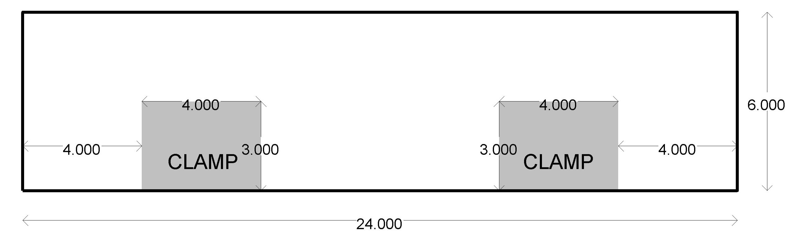
- To allow for proper clamping of modules, a space between 4 and 8 inches from each side and 3 inches in height shall be free and clear of any structure or components. Modules will be clamped with two clamps per end plate as show below.

Click to open diagram in new window.
3.0 Track
Properly constructed and maintained track is essential for smooth operation and reliable electrical connections. The following standards apply to all track used on Free-moS modules.
- S3.1
- Modules shall use either flex track or hand-laid track. All rails on the module shall be made of Nickle-Silver.
- S3.2
- The centerline of all tracks should be 4 inches or more from the sides of a module or section at all times.
- S3.2.1
- When it is not possible to maintain a centerline of 4 inches from the side of a module, such as in curve modules, the scenery or fascia must be extended no less than 2 inches above the top of the module to prevent equipment from falling to the ground in the event of a derailment.
- S3.3
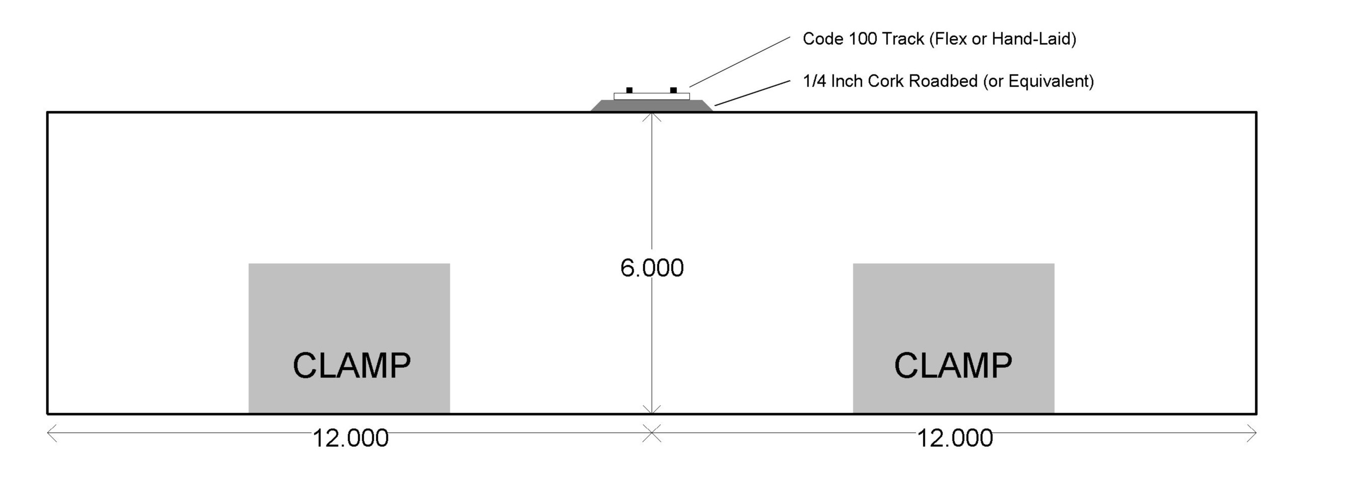
- On a single track module, the through route shall be centered on the 24 inch wide endplate.

Click to open diagram in new window.
- S3.4
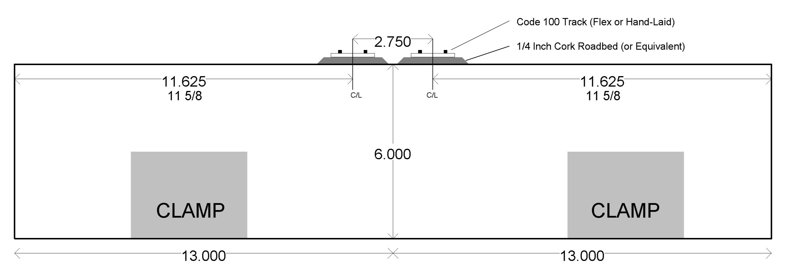
- On a double track module, the through route shall placed 2 and 3/4 inches apart at the centerline and centered on the 26 inch endplate. This will place the center line of each main line 11 5/8 inches from the side closest to each main line.

Click to open diagram in new window.
- RP3.4.1
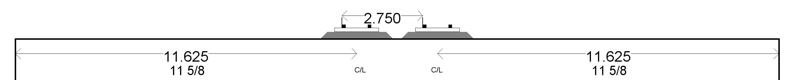
- Measuring at the center of the track is difficult but needs to be precise to align with other modules. Consider measuring from the outside of one rail to the outside of the same rail on the adjacent track. This will yield the same measurement as the center of the track.

Click to open diagram in new window.
- S3.5
- Track on the through route must be perpendicular, straight and level for 9 inches from the endplate. This is to allow for proper transitions of the track on adjacent modules.
- RP3.5.1
- The points of a turnout should not be placed with 9 inches of the endplate.
- S3.6
- Rail shall run to the end of the module with no more than 1/8 inch gap from the end of the module.
- S3.7
- Track on the through route shall be code 100 rail.
- S3.7.1
- It is recommended that Micro-Engineering rail be used for consistency on all modules
- S3.8
- Any track designated as a siding shall be a maximum of Code 100 and a minimum of Code 83 rail.
- S3.9
- The minimum code rail that can be used on track used in operations shall be Code 70.
- S3.10
- The minimum permitted curve radius on the through route shall be 42 inches. This includes all track that connects at both ends to a through route.
- S3.11
- Turnouts on the through route shall be #8 or larger.
- RP3.11.1
- The minimum turnout on a main line to a diverging, non-through route shall be #6. Turnouts not intersecting the main can be any size but should not be smaller than a #4.
- RP3.11.2
- The minimum wye turnout on a main through route can be a #6 so long as it has the same or greater frog angle than a #8 turnout.
- S3.12
- There shall be a minimum of 18 inches between reverse curves on a main through route.
- RP3.12.1
- It is recommended that any curves in the main through route contain a minimum of 9 inches of easement to avoid cars from jerking into a curve.
4.0 Electrical Wiring
Proper wiring is essential for reliable operation of the layout. The following standards apply to all wiring used on Free-moS modules. Please pay particular attention to S4.6 and S4.7 to allow proper connections between modules.
- S4.1
- On single track modules, there shall be 2 pairs of bus wires consisting of 1 track bus and 1 accessory bus.
- RP1.1.1
- It is recommended that on modules with non-mainline track, such as sidings or industries, that a secondary bus be added to allow for future expansion to add detection for a signal system.
- S4.2
- On double track modules, there shall be 3 pairs of bus wires consisting of 2 track buses, one for each main line, and 1 accessory bus.
- RP4.2.1
- A separate bus for each main line will allow for detection and signalling should this be added in the future. It is acceptable to use jumpers at an endplate to connect both buses during setup.
- RP4.2.2
- On single track to double track modules, also known as 2-to-1 modules, it is permitted to connect both track buses to the same plug on the single track end. However, you should plan for future addition of signal detection if you wish to add signals to your module.
- S4.4
- All Bus wires shall be 14 gauge or larger stranded wire.
- RP4.4.1
- It is recommended that the free ends, or pigtails, at each endplate be a minimum of 12 inches, 18 inches if these free ends are not mounted in the center of the endplate. take care not to mount your free ends within the clamping area described in S2.12 above.
- S4.5
- There shall be a 4 or 6 (or larger) position barrier strip at each end of the module that can accommodate all of the bus wires. Bus wires and free ends must terminate in a barrier strip at each endplate.
- S4.6
- The Track Bus shall be terminated on all ends with a pair of Anderson Powerpole PP15-45 Standard Housing incorporating a 30 amp power contact for use with 12-14 gauge wire. The PP15-45 connectors shall be stacked vertically (hood up, tongue down).
- While facing each end of your module, remember the left over rule. The top wire on each plug will connect to the left hand rail. On modules with multiple ends, follow this rule for every end and for each main line track. Remember to disregard the orientation of any other end as you wire each end.
Single Track Wire Diagram

Double Track Wire Diagram

- S4.7
- The Accessory Bus shall be terminated on all ends with a pair of Anderson Powerpole PP15-45 Standard Housing connectors incorporating a 30 amp contact for use with 12-14 gauge wire. The PP15-45 connectors shall be stacked horizontally (tongue-to-tongue, hood-to-hood).
- S4.9
- All track feeders shall be 24 gauge or larger stranded wire, but no longer than 6 inches to the Track Bus to avoid voltage loss.
- S4.10
- All items attached to the Accessory Bus must be able to able accommodate a 16V AC current. A bridge rectifier and filtering capacitor can be used to convert the AC to DC power as needed.
- RP4.10.1
- The Accessory Bus may be connected to a DCC system to carry a DCC signal.
- RP4.10.2
- AC Power was chosen for the Accessory Bus as it will prevent the loss of voltage better than DC.
- S4.11
- The Anderson PowerPole PP15-45 connectors for the track and accessory buses shall be separate sets of connectors at each endplate.
5.0 Control
Notice: As of January 17th, 2025, a control mechanism has not been decided. It is desired that any DCC system can be used so we are researching plans that do NOT tie the layout to one brand of DCC. At this time, no DCC network type cabling will be required on modules.
- S5.1
- Future control details will be added here.
- S5.2
- For a given turnout, controls must be located on all sides of the module or module section, excepting any endplates.
- RP5.2.1
- If surface mounted ground throws are used, they should be easily accessible from all sides of a module. Ground throws must be kept in working order or may be spiked during a setup.
- RP5.2.2
- It is recommended that all turnouts on a main line through route are powered from an under table switch motor such as a Tortoise, and that the controls have some sort of visual indication for the state of the turnout. For example, a turnout set for the main through route should show a green indication, otherwise it should show a red indication.
6.0 Scenery
Scenery is an important aspect of any model railroad layout. It helps to create a sense of realism and adds visual interest to the module. The following standards apply to all scenery used on Free-moS modules.
Notice: Until S6.5: Ballast Color is selected, it is acceptable and recommended that your module has no scenery during setups. Please consider painting the tops of your modules a basic dirt color or light brown.
- S6.1
- Scenery shall be prototypical and realistic, with attention to detail in structures, landscapes, and other elements. Scenery should be appropriate to the location and era being modeled, with accurate representations of buildings, foliage, and other features.
- S6.2
- Scenery should be designed to enhance the overall appearance of the module and create a sense of realism for operators and spectators. The scenery should be well-crafted and detailed, with a focus on creating a visually appealing and engaging environment.
- S6.3
- Scenery should be durable and long-lasting, with materials and techniques that are suitable for the demands of model railroading. Scenery should be able to withstand handling and transportation, as well as the effects of time and use.
- S6.4
- The plywood or foam tops of all modules shall be covered with a basic ground cover to avoid the plywood central appearance during public shows.
- S6.5
- Scenery at the endplate shall have a flat profile 3/8 inch below the top of the rail on the through route.
- S6.6
- Discussion Needed. Ballast color on the through route has not been decided as of January 17th, 2025. It is best that track is not ballasted at this time.
- S6.7
- General Module Fascia Color shall complement the scenery, such as green for a module with grass or brown for a module with sand. There shall be no standard color for the sides of module.
- RP7.6.1
- It is recommended that the fascia to not be painted black or gray as this tends to draw attention from the scenery on the module. Remember, we want spectators looking at the top of the module, not the sides.
- RP7.6.2
- It is recommended that the endplates of the module and sections remain unpainted to avoid sticking and paint transfer when clamped together. If you desire to paint your endplates, please use a flat latex paint.
Operations
- S7.1
- Modules shall be designed to allow for prototypical operations, including switching, running, and other activities. The track plan and scenery should be laid out to support realistic operations, with appropriate locations for industries, yards, and other features.
- S7.2
- Modules should be designed to accommodate a variety of operating scenarios, including continuous running, point-to-point operations, and switching puzzles. The track plan and scenery should be flexible enough to support different types of operations, with opportunities for operators to make decisions and interact with the layout.
- RP7.2.1
- Do not overdo it! It is not recommended to fill your module with track and turnouts. Smaller is better. Research prototype locations to see how the real railroads do it.
- S7.3
- Modules should be designed to allow for multiple trains to operate simultaneously, with provisions for passing sidings, crossovers, and other features that enable trains to interact with each other. The track plan and wiring should support multiple trains running at different speeds and in different directions, with the ability to control each train independently.
Revision History
The Free-moS standard is periodically updated to reflect changes in technology and modeling practices. The revision history of the standard includes a list of changes and updates that have been made over time, along with the reasons for those changes. The revision history is maintained by the Free-moS Standards Committee, which is responsible for overseeing the development and implementation of the standard.
- January 20th, 2025: Added S3.2.1 to require fall protection when main line is less than 4 inches from the side.
- January 17th, 2025: Initial draft of the standard created.